

服务热线
13905146213
13905146213
025-57282268
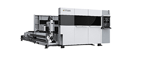
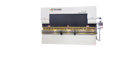
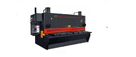
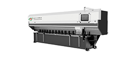
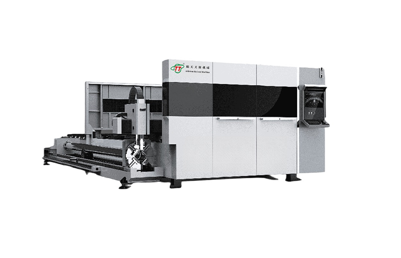
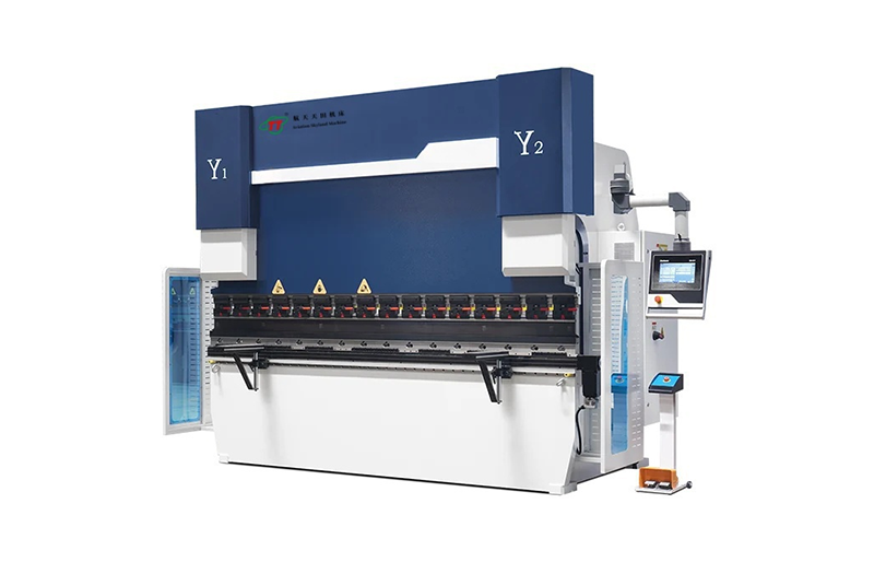
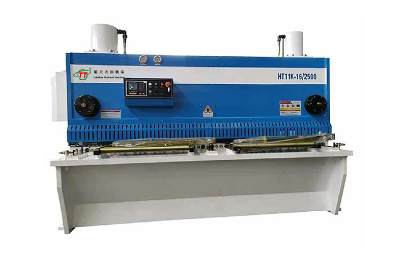
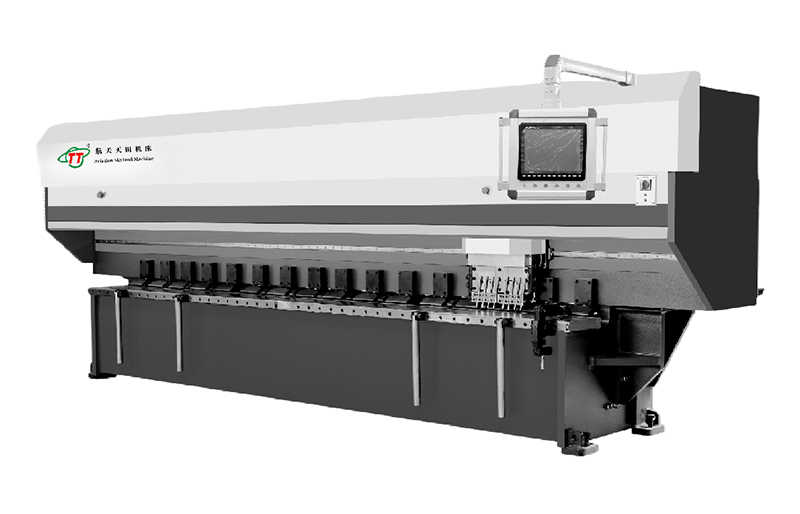
热门关键字: 光纤激光切割机系列 折弯机系列 剪板机系列 开槽机系列 冲床/联合冲剪机系列
订购热线:13905146213

质量稳定,性能突出
高功率激光切割设备质量稳定可靠
性能突出能满足客户10多小时以上的长时间切割加工需求

现代化生产基地,拥有研发中心、营销中心、品控检测中心
数百余台加工设备,完善生产、品检、装配车间

每一件产品都通过现代化设备精加工而成,质量品质通过公司严控检测完全达到产品使用标准。
严格品质检测、跟踪检验。

专业的客户服务团队,售前提供一对一技术指导
售中:提供专业的订单跟进汇报
售后:客服7*24小时全天候在线,为您解决技术问题
CAR INDUSTRY
HARDWARDE PRODUCTS
KITCHEN WARE
SHEET METAL
CUBICLE
CHASSIS CABINETS
LIGHTING INDUSTRY
ADVERTISING INDUSTRY
CRAFTGIFT
PRECISION MACHINERY
SPORTS GOODS
GLASSES INDUSTRY

日常保养 机床日常工作前后随时进行保养 1.严格按照操作规程履行操纵。 2.每次开机前按润滑图表要求守时、定点、定量加润滑油。 3.开动折弯机机器作空转若干循环,使机器运行平稳,不能有异常噪音,和液压油渗漏情况。 4.机床必须经常贯穿连接洁净,并经常检查电器部分是否正常。 5.平常必须做到人离机停。 6.每天下班前对机床加油润滑及清洁机床,润滑导轨。 一级保养 机床运行三个月进行一级保养,以操作工人为主,维修工人配合进行。 首先切断电源,然后进行保养工作(见下表)。 序号 保养部位 保养内容 一 外观保养 1、擦拭机床,要求无油污。 2、配齐缺损零件。 3、紧固松动螺钉。 二 传动 1、检查、调整传动带。 2、清洁滚珠丝杆。 三 滑块/油缸 1、调整滑块两侧导轨间隙。 2、检···
+MORE【 企业使命 】不懈努力,设计制造出更完美的产品
【 企业愿景 】航天天田产品、做航天天田人、做航天天田精品
【 企业核心价值观 】诚信、协作、务实、创新