
服务热线
13905146213
13905146213
025-57282268

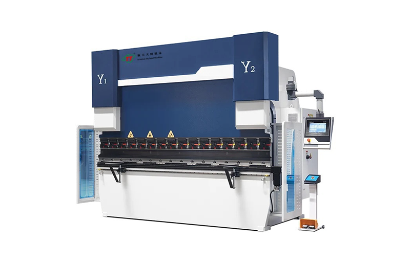


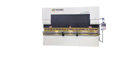
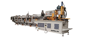
HTB-DA66W(DA69W)系列电液伺服数控折弯机
HTB-DA66W(DA69W)系列电液伺服数控折弯机标准配置是4+ 1轴(Y1/Y2/X/V+R机械工作台补偿),可选配置至“8 + 1轴”(Y1/Y2/X1/X2/Z1/Z2/V1/V2+R轴机械工作台补偿)电液伺服数控折弯机的工作原理融合了多轴联动控制、电液伺服驱动以及独特的机械工作台补偿机制,具体如下:
1. 电液伺服驱动原理:该折弯机采用先进的电液伺服系统。数控系统会根据操作人员预先输入的加工参数(如板材材质、厚度、折弯角度、折弯长度等),经过精确的计算和分析后,向电液伺服阀发出对应的电信号。电液伺服阀依据这些电信号来精确控制液压油的流量和流向,进而驱动液压缸,实现对滑块运动的精准控制,包括滑块的下降速度、停止位置以及施加的压力等,以确保折弯操作的准确性和稳定性。
2. 8 + 1轴联动控制:“8 + 1轴” 意味着该折弯机具备多个可独立运动且又能协同工作的轴。其中8轴通常涵盖了滑块的垂直运动轴(控制上下行程以实现折弯动作)、后挡料的多个定位轴(用于精确确定板材的位置,保证每次折弯的尺寸精度)等。另外1轴可能是指特定的辅助轴或具有特殊功能的轴。这些轴在数控系统的协调和控制下,能够按照预设的程序和轨迹进行联动运动,使得折弯机可以处理各种复杂的折弯任务,满足不同形状和尺寸的板材加工需求。
3. 机械工作台补偿原理:在折弯过程中,由于工作台在承受较大压力时会产生一定的变形,这种变形会影响到折弯的精度。为了克服这一问题,该折弯机配备了机械工作台补偿装置。当滑块向下运动对板材施加压力进行折弯时,工作台的变形情况会被检测装置实时监测(可能通过传感器等设备)。数控系统根据检测到的变形数据,计算出需要补偿的量,并控制机械补偿装置(如通过丝杆、螺母机构等)对工作台的相应部位进行微调,增加或减少工作台的局部高度,从而补偿因工作台变形而导致的折弯误差,确保折弯角度和尺寸的高精度,提高加工质量。
4. 模具配合与折弯过程:折弯机上安装有特定形状和尺寸的上、下模具。上模具固定在滑块上,下模具安装在工作台上。当滑块在电液伺服系统的驱动下向下运动时,板材被放置在上、下模具之间,随着滑块的继续下压,板材在模具的作用下发生塑性变形,逐渐达到所需的折弯角度和形状。在这个过程中,各轴的精确运动和机械工作台补偿机制共同作用,保证了折弯的准确性和一致性 。
5. 数控系统的核心作用:数控系统是整个折弯机的大脑,它不仅负责接收和处理操作人员输入的各种加工参数,还能对电液伺服系统、各轴的运动以及机械工作台补偿装置等进行实时监控和精确控制。通过内置的算法和程序,数控系统能够根据不同的加工任务,自动调整各部分的工作状态,实现自动化、智能化的折弯加工过程,同时还具备故障诊断、数据记录和存储等功能,方便操作人员进行设备维护和生产管理。
一、设备特点:
本机床采用荷兰进口DELEM DA66W(DA69W)数控系统,具有人性化吊臂;基于实时的windows操作系统,三维彩色图形折弯机数控系统;
采用荷兰 DELEM公司 DA66W(DA69W)数控系统为使用者提供友好操作界面,高效率编程方式,和引以自豪稳定性集成于一体,将大大提高数控折弯机的工作效率。
图形编程技术秉承DELEM 的编程优势,真实比例显示工件、模具和机床。
数控系统包括DA65W2D或DA69W3D数控系统图形编程软件,具有折弯工序自动计算、工件干涉检测和自学习数据库,数据库运用将大大提高折弯精度。
全功能2D或3D图形编程软件清晰展示真实机床模具配置以及折弯实现的可行性。
采用更高效率算法优化整个Y轴、X轴、R轴和补偿V轴工作循环,使得Y轴、X轴、R轴和补偿V轴循环的周期缩短,提高机床工作效率,同时对Y轴调整和控制更为方便。
二、设备基本配置


三、设备性能介绍:(设备标配)
1、整机采用钢板焊接结构,并经整体振动处理;
2、一次装夹整体加工,保障机身的刚性和加工精度;
3、标准为数控8+1轴,Y1 、Y2、 X1、X2、R1、R2、Z1、Z2+ V;
4、电液伺服系统配合德国HEIDENHAIN(海德汉)进口或意大利光栅尺GIVI,折弯精度更高;
5、液压挠度自动补给,消除滑块弯形对工件质量的影响;
6、原装进口集成液压控制系统减少管路安装,克服漏油;
7、后挡料采用台湾HIWIN(上银)直线导轨及滚珠丝杠驱动,速度更快精度更高;
8、上模选用快速夹紧,减轻工人劳动强度,提高生产效率;
9、可选配荷兰DELEM DA66W(DA69W)系统;
10、可根据用户需要,后定位可控制八轴;
11、可选配液压上模夹紧。
****1、最高可选配至12+1轴,增加数控轴另议。
****2、开启高度及喉口深度可根据客户选择,承接非标设备定制。
四、数控折弯机技术参数表(Technical Parameter Table of CNC Press Brake):
| 型 号Equipment Model | 公称力Nominal pressure | 工作台长度 Workbench length | 力柱间距Distance between columns | 喉口深度Throat depth | 滑块行程Slider stroke | 最大开启高度Maximum opening height | 主电机功率Main motor power | 外型尺寸Overall dimensions |
| (KN) | (mm) | (mm) | (mm) | (mm) | (mm) | (KW) | 长*宽*高(mm) | |
| 40/2200 | 400 | 2200 | 1850 | 250 | 100 | 350 | 5.5 | 2560*1300*1900 |
| 40/2500 | 400 | 2500 | 2150 | 250 | 100 | 350 | 5.5 | 2860*1300*1900 |
| 50/2500 | 500 | 2500 | 2150 | 250 | 100 | 350 | 5.5 | 2860*1300*1900 |
| 63/2500 | 630 | 2500 | 2150 | 250 | 120 | 350 | 5.5 | 3060*1380*2200 |
| 63/3200 | 630 | 3200 | 2580 | 250 | 120 | 350 | 5.5 | 3860*1430*2200 |
| 80/3200 | 800 | 3200 | 2580 | 320 | 120 | 350 | 7.5 | 3860*1510*2300 |
| 80/4000 | 800 | 4000 | 2980 | 320 | 120 | 350 | 7.5 | 4660*1430*2300 |
| 100/3200 | 1000 | 3200 | 2580 | 320 | 130 | 435 | 7.5 | 3860*1480*2450 |
| 100/4000 | 1000 | 4000 | 2980 | 320 | 130 | 450 | 7.5 | 4660*1530*2450 |
| 125/3200 | 1250 | 3200 | 2580 | 320 | 130 | 435 | 11 | 3900*1550*2550 |
| 125/4000 | 1250 | 4000 | 2980 | 320 | 130 | 435 | 11 | 4500*1580*2550 |
| 160/3200 | 1600 | 3200 | 2580 | 320 | 150 | 470 | 11 | 3900*1600*2800 |
| 160/4000 | 1600 | 4000 | 3000 | 320 | 150 | 470 | 11 | 4720*1650*2850 |
| 160/5000 | 1600 | 5000 | 4000 | 320 | 150 | 470 | 11 | 5760*1750*;2900 |
| 160/6000 | 1600 | 6000 | 5000 | 320 | 150 | 470 | 11 | 6700*1780*3000 |
| 200/3200 | 2000 | 3200 | 2580 | 400 | 200 | 500 | 15 | 3900*1650*2800 |
| 200/4000 | 2000 | 4000 | 3000 | 400 | 200 | 500 | 15 | 4560*1650*2800 |
| 200/5000 | 2000 | 5000 | 4000 | 400 | 200 | 500 | 15 | 5700*1700*2900 |
| 200/6000 | 2000 | 6000 | 5000 | 400 | 200 | 500 | 15 | 6600*1700*3000 |
| 250/4000 | 2500 | 4000 | 3000 | 400 | 200 | 560 | 18.5 | 4700*1700*3000 |
| 250/5000 | 2500 | 5000 | 4000 | 400 | 200 | 560 | 18.5 | 5760*1700*3100 |
| 250/6000 | 2500 | 6000 | 5000 | 400 | 200 | 560 | 18.5 | 6700*1800*3150 |
| 300/4000 | 3000 | 4000 | 3000 | 400 | 250 | 560 | 22 | 4660*2000*3000 |
| 300/5000 | 3000 | 5000 | 4000 | 400 | 250 | 560 | 22 | 5700*2000*3100 |
| 300/6000 | 3000 | 6000 | 5000 | 400 | 250 | 560 | 22 | 6720*2100*3200 |
| 600/4000 | 4000 | 4000 | 3000 | 400 | 250 | 570 | 22 | 4700*2000*3100 |
| 400/5000 | 4000 | 5000 | 4000 | 400 | 250 | 570 | 22 | 5760*2000*3200 |
| 400/6000 | 4000 | 6000 | 5000 | 400 | 250 | 570 | 22 | 6760*2100*3300 |
| 500/4000 | 5000 | 4000 | 3000 | 400 | 250 | 590 | 37 | 4760*2300*3500 |
| 500/5000 | 5000 | 5000 | 4000 | 400 | 250 | 590 | 37 | 5760*2300*3500 |
| 500/6000 | 5000 | 6000 | 5000 | 400 | 250 | 590 | 37 | 6760*2300*3600 |
| 600/4000 | 6000 | 4000 | 3000 | 400 | 250 | 610 | 45 | 4760*2400*3600 |
| 600/5000 | 6000 | 5000 | 4000 | 400 | 250 | 610 | 45 | 5800*2400*3600 |
| 600/6000 | 6000 | 6000 | 5000 | 400 | 250 | 610 | 45 | 6860*2500*3700 |
注:本资料所列数据为参考数据,如与机床实际数据不符,应以机床实际数据为准,
以上参数如有变动,恕不另行通知,本公司保留对此资料的最终解释权!