


服务热线
13905146213
13905146213
025-57282268

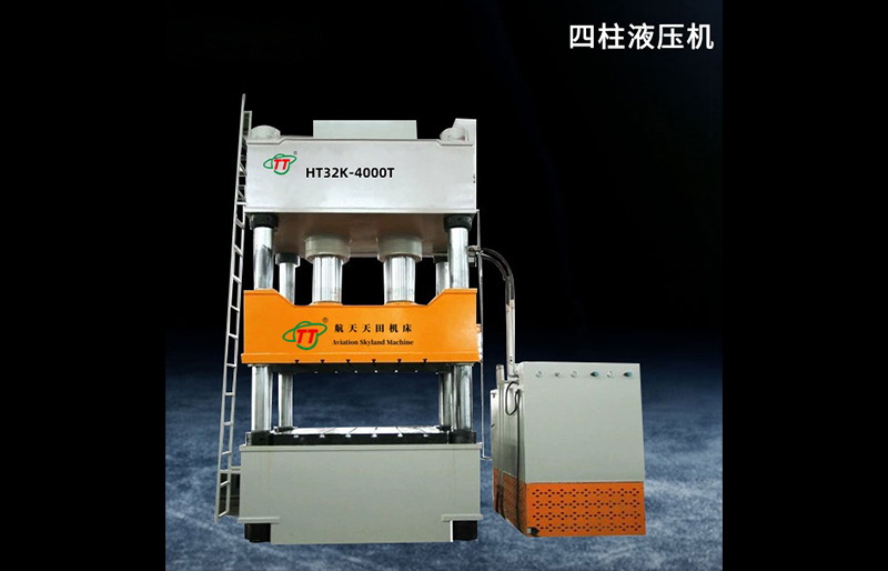


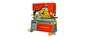
HT28 系列油缸带顶出的四柱油压机性能介绍:
一、用途:
HT28系列油缸带顶出的四柱液压机适用于可塑性材料的压制工艺,如冲压、弯曲、翻边、薄板拉伸等,还适用于校正、压装、粉末制品成型以及非金属材料的压制成型。
二、特点:
HT28 油缸带顶出的四柱油压机通常具有以下性能特点:
结构坚固稳定:四柱式结构设计,搭配合理的油缸配置,能够承受较大的工作压力,运行稳定可靠。机身采用优质材料制造,经过严格的加工和处理工艺,具有良好的刚性和强度,可确保长期使用过程中设备的精度和稳定性。
顶出功能实用:配备的油缸顶出装置,顶出力大小适中,可满足多种工艺需求。顶出行程可根据实际加工情况进行调整,操作方便。顶出动作平稳,能够精确控制顶出的位置和力度,保证工件的加工质量和生产效率。
液压系统高效:采用先进的液压系统,由性能可靠的油泵、油缸及各种液压阀等组成。系统具有良好的密封性,可有效防止泄漏,保证液压油的清洁度,延长液压元件的使用寿命。液压系统的压力、流量可根据工艺要求进行调节,实现快速、稳定的工作循环,提高生产效率。
电气控制智能:配备智能化的电气控制系统,操作界面简洁明了。可实现手动、半自动等多种操作模式,方便操作人员根据不同的加工要求进行选择。控制系统具有故障诊断和报警功能,能够及时发现和排除故障,保证设备的正常运行。
安全性能良好:设置了多种安全保护装置,如急停按钮、上下限位开关等,可有效防止设备在运行过程中出现意外情况,保障操作人员的人身安全和设备的正常运行。同时,设备的防护栏、防护罩等部件齐全,可避免操作人员接触到危险部位。
适用范围广泛:适用于金属材料的拉伸、弯曲、翻边、校正、压装等多种加工工艺,也可用于塑料、橡胶等非金属材料的成型加工。可根据不同的工艺要求,配备相应的模具,满足不同产品的生产需求。
维护保养方便:设备的结构设计便于维护和保养,各部件的安装位置合理,易于检查和维修。液压系统的元件布局紧凑,便于更换和调整。同时,设备的润滑系统可自动或手动进行润滑,减少部件的磨损,延长设备的使用寿命。
本系列液压机具有继电器控制和PLC控制两种电气控制系统,有调整、手动及半自动三种操作方式,可实现压和定制两种工艺方式。定压成型时及自动回程动作。工作台中间装有顶出装置,除顶出制品外,可作为液压垫用于反拉伸制件饿成型工艺,其他工作压力与行程,可根据工艺需要,在规定范围内调整。
三、HT28 油缸带顶出的四柱油压机主要由机身、液压系统、电气控制系统等部分组成,其工作原理如下:
动力传递:电机驱动油泵运转,将液压油从油箱中吸出并加压,形成高压油液。高压油液通过油管输送到各个液压元件,为油压机的工作提供动力。
主油缸工作:当需要进行压制工作时,电气控制系统控制相应的电磁换向阀动作,使高压油液进入主油缸的无杆腔,推动主油缸的活塞下行,从而带动滑块(连接在活塞上)向下运动,对放在工作台上的工件施加压力,实现压制工艺。同时,主油缸有杆腔的油液通过电磁换向阀流回油箱。在压制过程中,可通过调节液压系统中的溢流阀来控制油液压力,以满足不同的压制力要求。
顶出油缸工作:当压制完成需要顶出工件时,电气控制系统控制另一组电磁换向阀动作,使高压油液进入顶出油缸的无杆腔,推动顶出油缸的活塞向上运动,顶出杆伸出,将工件从模具中顶出。顶出油缸有杆腔的油液则通过电磁换向阀流回油箱。顶出的力度和行程可通过调节相应的压力阀和行程开关来控制。
回程:压制和顶出完成后,电磁换向阀再次动作,使主油缸和顶出油缸的油路换向。主油缸的有杆腔进入高压油液,推动活塞上行,滑块回程至初始位置;顶出油缸的有杆腔进入高压油液,使顶出杆缩回至初始位置。此时,油缸无杆腔的油液流回油箱。
保压与泄压:在压制过程中,若需要保持一定的压力一段时间,液压系统可通过保压回路实现。保压时,油泵停止供油,由蓄能器或单向阀等元件保持系统压力。当工作完成后,需要对系统进行泄压,以防止在拆卸模具或进行其他操作时发生危险。泄压过程通过相应的泄压阀来实现,缓慢释放系统中的高压油液,使系统压力降至安全范围。
四、技术参数(Technical Parameters):
| 参数名称 | 单位 | 四柱液压机 | ||||||||||||||||
HT 32-40A | HT 32-63 | HT 32-100 | HT 32-100A | HT 32-160 | HT 32-160C | HT 32-200 | HT 32-315 | HT32-400 | HT 32-500 | HT 32-500C | HT 32-630 | HT 32-800 | HT 32-1000 | HT 32-1250 | HT 32-1600 | |||
| 公称力 | KN | 400 | 630 | 1000 | 1000 | 1600 | 1600 | 2000 | 3150 | 4000 | 5000 | 5000 | 6300 | 8000 | 10000 | 12500 | 16000 | |
| 顶出力 | KN | 120 | 190 | 190 | 190 | 240 | 240 | 400 | 630 | 800 | 1000 | 1000 | 1000 | 1600 | 2000 | 2000 | 2000 | |
| 液体最大工作压力 | Mpa | 25 | 25 | 25 | 25 | 25 | 25 | 25 | 25 | 25 | 25 | 25 | 25 | 25 | 25 | 25 | 25 | |
| 滑块行程 | mm | 350 | 450 | 600 | 600 | 700 | 700 | 700 | 800 | 800 | 900 | 900 | 900 | 800 | 900 | 900 | 900 | |
| 顶出行程 | mm | 150 | 200 | 200 | 200 | 200 | 200 | 250 | 300 | 300 | 350 | 350 | 350 | 450 | 450 | 450 | 450 | |
| 滑块下平面至工作台面最大距离 | mm | 700 | 800 | 900 | 900 | 1000 | 1000 | 1100 | 1250 | 1350 | 1500 | 1500 | 1600 | 1600 | 1600 | 1600 | 1600 | |
| 滑块行程速度 | 空 程 下 行 | mm/s | 50 | 100 | 22 | 100 | 100 | 100 | 100 | 100 | 100 | 100 | 100 | 100 | 80 | 80 | 80 | 80 |
| 工 作 | mm/s | 25 | 25 | 14 | 16 | 10 | 10 | 18 | 12 | 10 | 15 | 15 | 12 | 12 | 10 | 6-10 | 6-10 | |
| 回 程 | mm/s | 50 | 80 | 50 | 80 | 50 | 50 | 80 | 60 | 45 | 80 | 80 | 50 | 50 | 50 | 45 | 40 | |
| 工作台尺寸 | 左 右 | mm | 500 | 560 | 680 | 680 | 750 | 1000 | 950 | 1250 | 1200 | 1400 | 2200 | 1400 | 1500 | 1530 | 1700 | 2000 |
| 前 后 | mm | 460 | 500 | 580 | 580 | 640 | 800 | 900 | 1120 | 1200 | 1400 | 1400 | 1200 | 1400 | 1600 | 1600 | 1600 | |
| 机器外形尺寸 | 左 右 | mm | 1160 | 2400 | 2500 | 2500 | 2700 | 2700 | 2825 | 3235 | 3235 | 4060 | 6500 | 4200 | 4800 | 5250 | 5250 | 5800 |
| 前 后 | mm | 900 | 1400 | 1500 | 1500 | 1700 | 1700 | 2600 | 2200 | 2200 | 3525 | 3800 | 4200 | 4000 | 3800 | 3800 | 4000 | |
| 地面上高度 | mm | 2250 | 3100 | 2950 | 3150 | 3400 | 3400 | 3725 | 4295 | 4500 | 4995 | 4740 | 5600 | 6000 | 5800 | 6000 | 6200 | |
| 电机 总功率 | Kw | 4 | 7.5 | 7.5 | 7.5 | 7.5 | 7.5 | 15 | 15 | 15 | 30 | 30 | 45 | 60 | 75.5 | 75.5 | 75.5 | |
| 机器重量 | Kg | 2000 | 3000 | 4000 | 4000 | 6000 | 6000 | 11000 | 14000 | 22000 | 28000 | 38000 | 34000 | 40000 | 48000 | 60000 | 82000 | |
备注:本资料所列数据为参考数据,如与机床实际数据不符,应以机床实际数据为准,
以上参数如有变动,恕不另行通知,本公司保留对此资料的最终解释权!